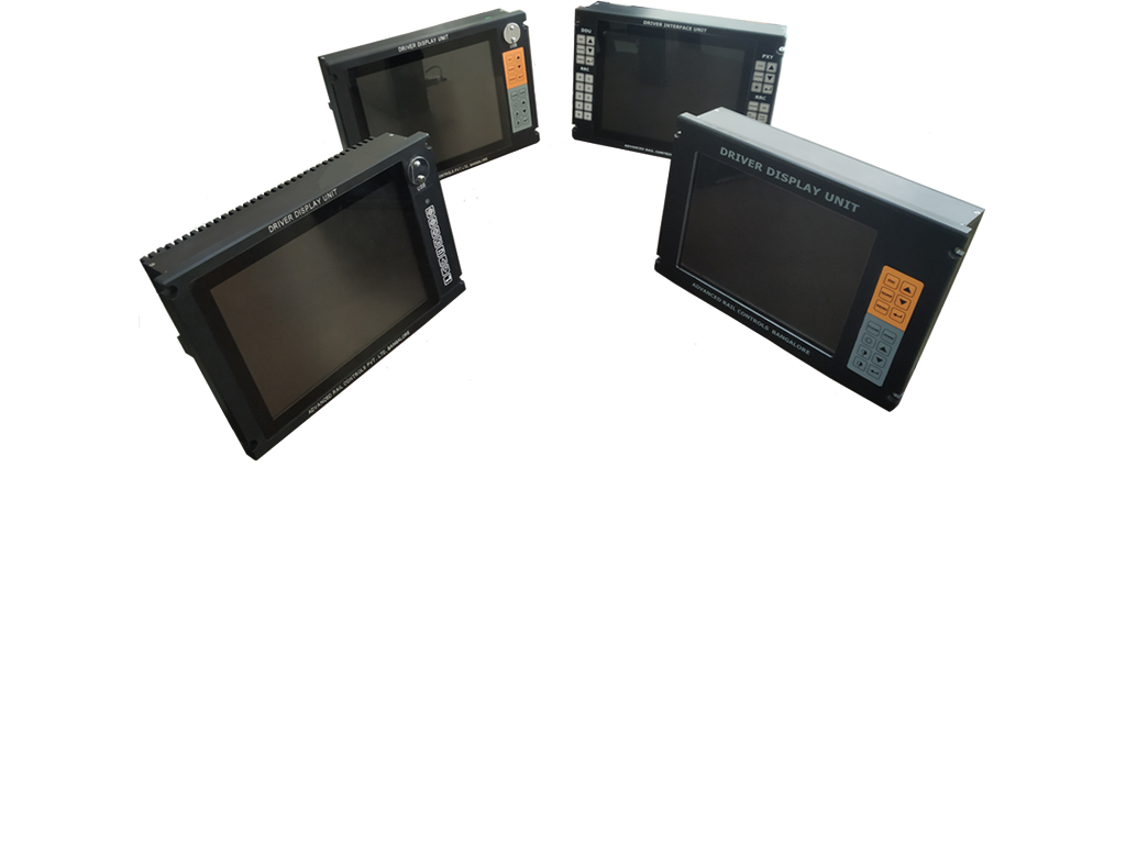
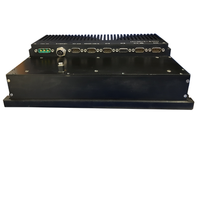
DRIVER DISPLAY UNIT (DDU)
The Driver Display Unit (DDU) is a man machine interface device able to communicate with locomotive control system through MVB. It Made as a panel mount equipment with LED backlit 10.4” LCD screen provides better readability even during daylight conditions, thanks to brightness control. Various fault messages and system generated prompts are displayed on screen. The DDU has various pre-defined screens which can be used for investigative monitoring.
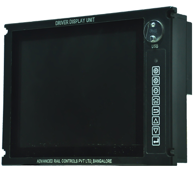
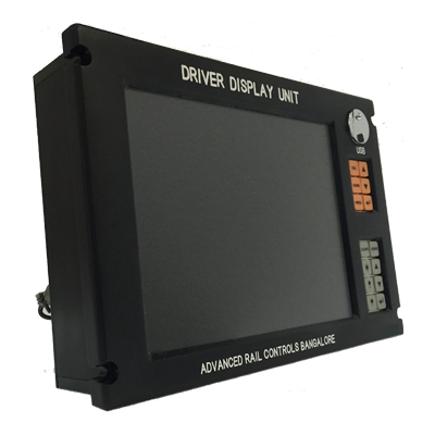
Linux Based DDU
The Driver Display is 10.4 inch ARM controller based capacitive touch screen and fanless design. Touch screen has resolution of 1024 X 768 with keypad support. It communicates with Vehicle Control Unit through MVB to display various locomotive parameters. USB, RS232, RJ45 Interface is available. It supports ESD/EMD MVB Communication.
Linux Based DDU with Diagnosis
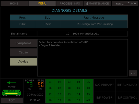
This Display is similar to Linux DDU with internal flash to store the fault and conditon data which is generated from Vehicle Control Unit. USB port is provided to extract fault messages from DDU for analysing the fault.
EMU MEMU and Vande Bharat
This is Linux DDU is support MEMU, EMU and Vande Bharat requirement. Its support MVB and Ethernet communication. Extra USB port is provided to store internal parameters.
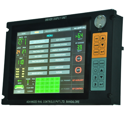
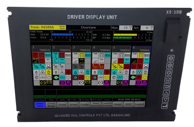
DOS Based DDU
The Driver Display provides 800x600 VGA graphic and works as a man machine interface. it uses 10.4” LCD TFT display. Driver is able to navigate through the menu using dedicated function keys. USB drive facilitates data exchange.
The unique feature of this display is that it retains the 4x40 character display format of the existing WAG9/WAP7/WAP5 class of three phase locomotives of Indian Railways as well as provides a graphic mimic window
in which various process variables can be seen by selecting pre-defined screens using function keys. The display has both MVB and RS422 interface.
Driver Interface Unit
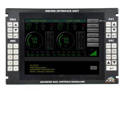
DIU is an interface between the driver and DPWCS. The DIU acts as terminal, simply to receive and display information from CCU (Control & Communication Unit) and send driver input to CCU. DIU has 1024 x 768 resolution capacitive touchscreen along with keypad support for redundancy. It supports ESD/EMD MVB or serial 485 Communication.
Key Features
DOS Based DDU
- 10.4" LCD display, LED backlight, variable intensity and fully enclosed IP65
- MVB interface with vehicle control, provision of 4x40 LCD text pixy® screen for driver's convenience.
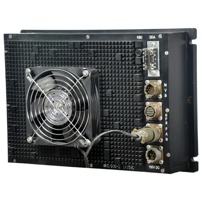
- Integrated external fan for chassis cooling, milled full aluminium anodised body.
- USB interface for data upload/download.
- Multiple pre set graphic screens for viewing MVB variables.
- Context sensitive troubleshooting directory pop up during fault. Can be used as a troubleshooting tool.
- Provision for viewing status of physical I/O signals.
- 800 X 600, 10.4" LCD TFT non touch screen display.
- OS : MS DOS.
- IEC-60571 compliant.
Linux Based DDU
- ARM based fanless design.
- ESD/EMD MVB communication support.
- USB RJ45 RS232 RS485 interface are available.
- Port Freshness and Signals View features available.
- 1024 X 768, 10.4" capacitive touch screen display.
- Screen brightness will automatically adjust to environment conditions.
- Multi language supported (English and Hindi).
- OS : Customize Linux.
- Hardware or Software can be customize for needs.
- IEC-60571 compliant.

Screens Details
1. SCREENS
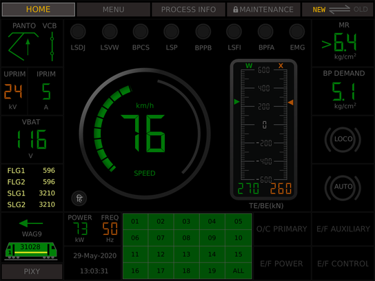
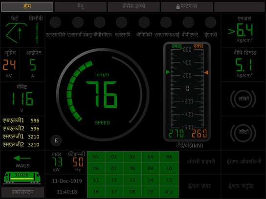
The Driver display has pre-defined dedicated screens in order to monitor real time process variables pertaining to a particular section or sub-system of the locomotive. However, such screens are meant for online monitoring by technical staff whenever required. The locomotive driver, however, needs to view the default screen only most of the times. The screens have been designed to take care of the specification requirement. The details of the screens are explained below.
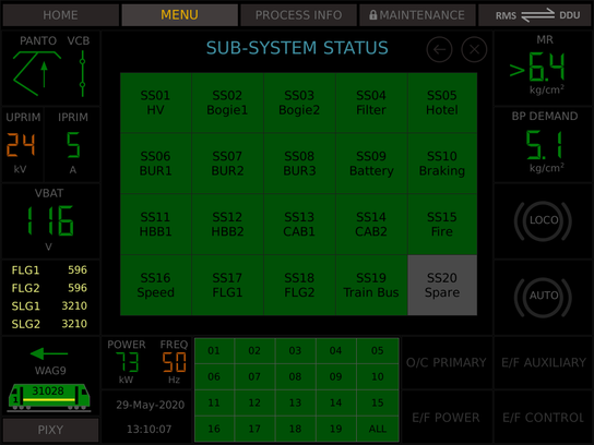
2. SUB-SYSTEM STATUS
In the sub-system status menu, the names of the sub-systems are listed. To navigate to default screen, press "HOME". To navigate to list of screens, press . The isolated sub-system will be shown in red.
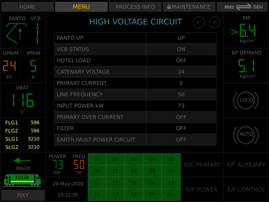
3. HIGH VOLTAGE CIRCUIT
In the high voltage circuit screen, Harmonic Filter status and Hotel Load status are additionally provided. Other variables are already available in the default screen. Hotel Load facility is available only in WAP7 & WAP5 class of locomotives.
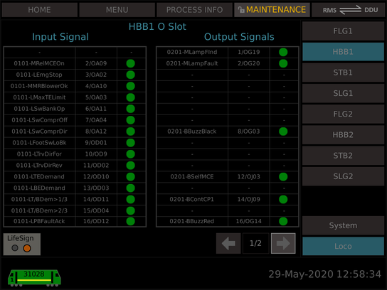
4. I/O SIGNALS
The physical input/output signals, both analog and digital, can be viewed using this multi-level screen. In this screen, the description of the signal, name used in FUPLA and the location of the signals and the actual value can be viewed (channel+slot+connector+pin number eg: 12/EA05 : means channel-12, E slot, A connector, pin-5). These screens will be quite useful for troubleshooting.
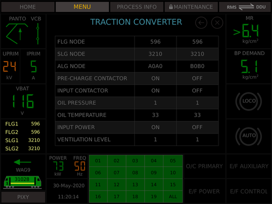
5. TRACTION CONVERTER
In traction converter screen, converter related parameters are displayed. The screen is split into two columns, one for each traction converter. The process variables displayed include pre-charge & input contactor status, oil pressure & temperatures, input power & ventilation level. Other displayed parameters are already available on default screen.
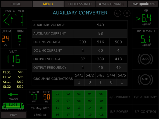
6. AUXILIARY CONVERTER
The Auxiliary Converter screen provides very vital process variable display about the BUR, which will help in easy trouble shooting. The variables include Auxiliary winding voltage, Total current in the auxiliary winding, dc link voltage & dc link current of each BUR, output voltage and output frequency. Please note that there is no direct signal available for the output voltage whereas the displayed value is calculated from dc link voltage and output frequency considering constant v/f relation. The screen also provides the status of BUR grouping contactors.
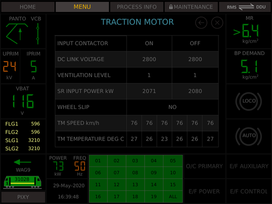
7. TRACTION MOTOR
The traction motor screen is also vertically split into two columns, one for 3 motors belonging to one bogie. The relevant process variables like input contactor status, dc link voltage, ventilation level, converter input power, wheel slip status, speed of each traction motor reported from speed sensor and temperature of each traction motor reported by the temperature sensor are displayed.
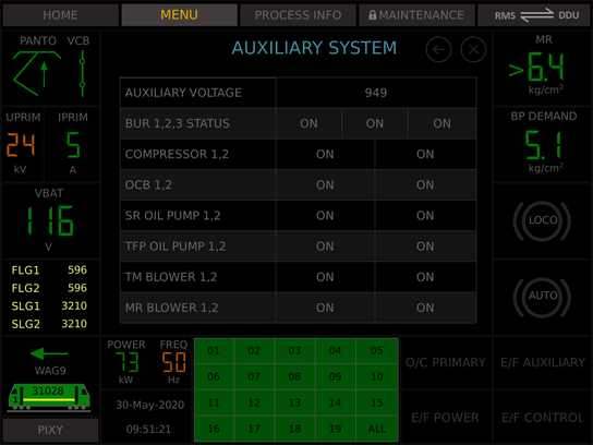
8. AUXILIARY SYSTEM
The auxiliary system screen essentially displays the status of various auxiliary machines, as to whether these are OFF or ON. It also indicates the BUR status and BUR input volatge. The auxiliary machines considered are Compressors (1,2), Oil Cooling Blowers (1,2), Oil Pump Converter (1,2), Oil Pump Transformer (1,2), Traction Motor Blower (1,2) & Machine Room Blower (1,2).
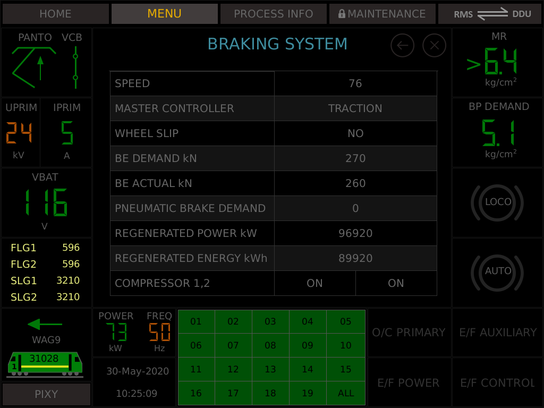
9. BRAKING SYSTEM
The braking system screen displays the process variables related to braking, which include locomotive speed, master controller position (traction/braking region), BE demand and BE Actual, Pneumatic Brake Effort demand (when regeneration fails), regenerated power & energy as well as status of compressor.
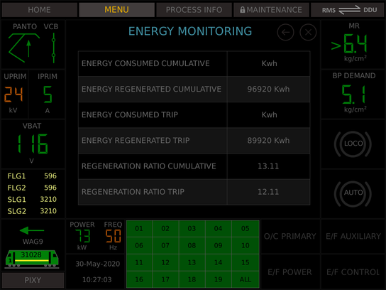
10. ENERGY MONITORING
The screen for energy monitoring displays the energy consumed and regenerated. The cumulative value is the one taken from the NVRAM of DIA computer, which is available on MVB. The trip energy is calculated by the driver display itself
from the time of switching ON. This value is not saved in any memory and will vanish once the locomotive is OFF. Trip energy can be used for comparison of driver performance under identical conditions of operation.
The regeneration ratio (energy regenerated/energy consumed) is calculated by the driver display and displayed. This factor also provides a measure of the efficiency of regeneration and is a good comparison tool.
11. TEMPERATURES
The temperature screen provides various temperatures recorded by sensors and the same can be compared with the converter input power. The temperatures of transformer oil, traction converter oil and traction motors are displayed alongwith converter input power for each bogie.
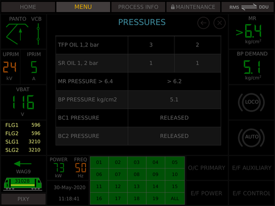
12. PRESSURES
This screen shows the pressure variables. It include Transformer oil pressure, converter oil pressure, MR pressure, BP pressure and status of BC1 & BC2.
Gallery
How System Works