FUNCTIONALLY EQUIVALENT PCBs
The present running 3-phase Electrical Locomotives using the design of MICAS S2 class of Electronic PCB’s are of late 1980’s vintage. Many components have already been declared obsolete by the OEM’s years ago. Due to this, the genuisness of many parts
which are currently being purchased is not very certain. The failures are likely to increase in future and maintenance could be a serious problem.
To overcome such difficulties we have undertaken re-design of MICAS S2 electronic PCB’s retaining the same functionality and straight-away interchangeable.
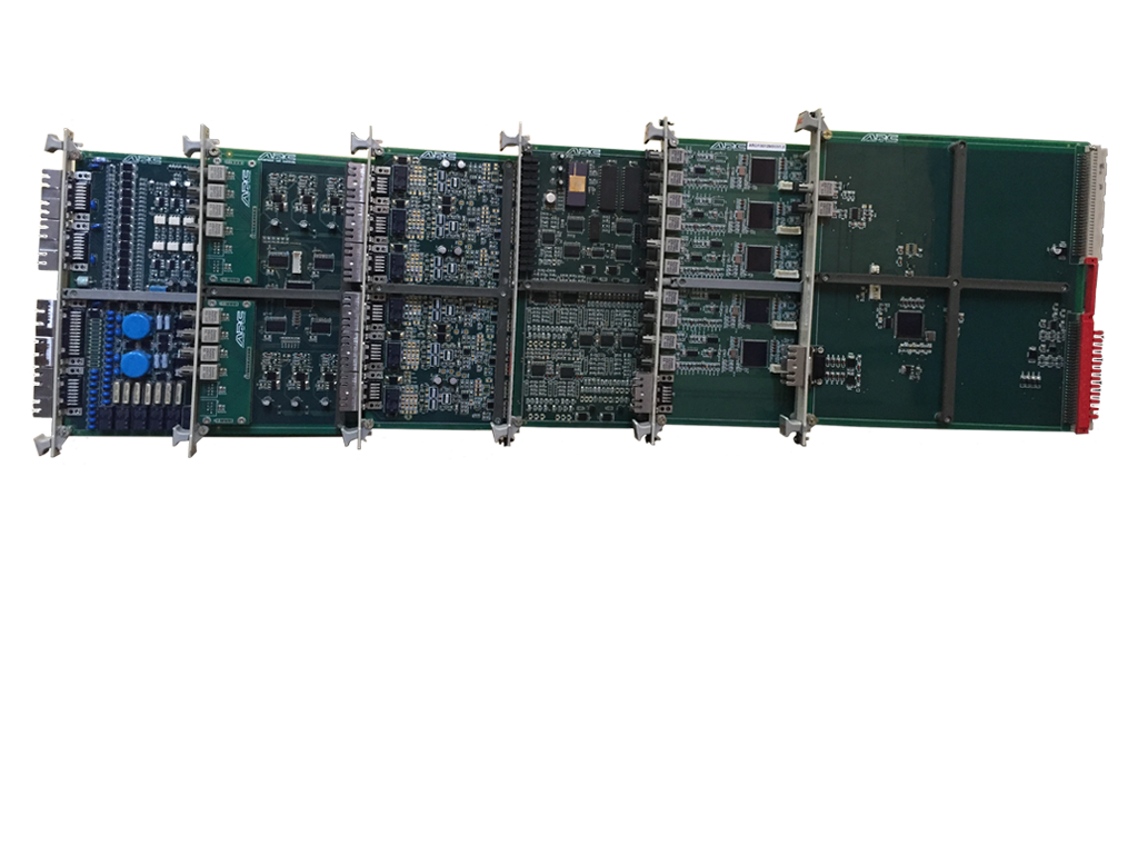
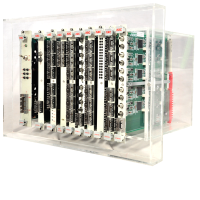
In this connection we have already developed 15 types of PCB’s namely:
Key Features
- 100% electrical, mechanical and functional compatibility with MICAS-S2 PCBs
- All obsolete electronic components eliminated
- Component count reduced by combining the logics in CPLD
MVB Optical single channel bus coupler
Since the MICAS vehicle bus transfers the data by using two different media, one with the local bus and other with the remote bus, this bus coupler serves as an electrical isolator and level converter between the local bus and remote bus. They regenerate the signals received by the local bus or the remote bus and transmit them on the remote bus or the local bus. A data conversion does not take place. If there is a continuous signal transmitter, the corresponding transmission direction will be switched off. This has single channel Optic fibre Transmitter and receiver.
MVB multiple redundant bus coupler
Since the MICAS vehicle bus transfers the data by using two different media, one with the local bus and other with the remote bus, this bus coupler serves as an electrical isolator and level converter between the local bus and remote bus. They regenerate the signals received by the local bus or the remote bus and transmit them on the remote bus or the local bus. A data conversion does not take place. If there is a continuous signal transmitter the corresponding transmission direction will be switched off. This has 5 channels of Optic fibre transmitter and Receiver.
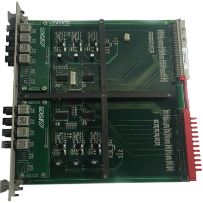
Analog Signal routing board
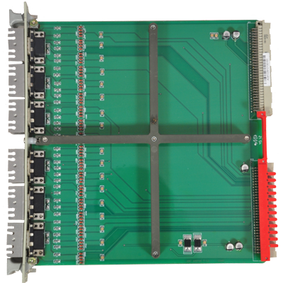
The new traction control electronics family realizes a new protection concept for electronics against electromagnetic interface. As a result, all the process signals are taken to the front panel of the individual electronic devices via screened cables and connectors. The signal routing board allows to connect up to 18 signals originating from the slightly emc populated peripheral range e.g. sensor signals via 6 sub-d connectors. These signals can be passed on to the rear edge connector. This card protects internal range against small disturbing pulses originating from the peripheral range by using simple RC filters.
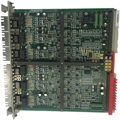
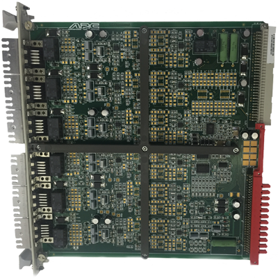
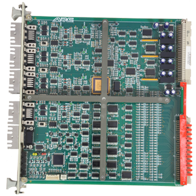
Signal Conditioning Card Line Converter
The signal conditioning board is used to transfer signals between internal and external zones. Signals from peripheral zone are fed to the front panel via shielded cables by means of 9-pin sub-D connectors. They are processed and relayed to the rack connectors. The six measuring channels for the LEM-Transducers essentially consists of an input amplifier, which can function as current or voltage amplifier, a low pass filter and a comparator. Two channels are equipped with both rectifier and integrator. The six measuring channels can also be used to monitor the gate unit supply. Furthermore the board allows the testing of both LEM-transducer by means of its test winding and the measuring channels.
Signal Conditioning Card Motor Converter
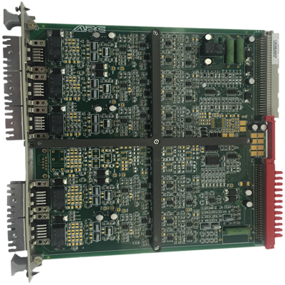
The signal conditioning board is used to transfer signals between internal and external zones. Signals from peripheral zone are fed to the front panel via shielded cables by means of 9-pin sub-D connectors. They are processed and relayed to the rack connectors. The six measuring channels for the LEM-Transducers essentially consists of an input amplifier, which can function as current or voltage amplifier, a low pass filter and a comparator. Two channels are equipped with both rectifier and integrator. The six measuring channels can also be used to monitor the gate unit supply. Furthermore the board allows the testing of both LEM-transducer by means of its test winding and the measuring channels.
Signal Conditioning Card Traction Converter
The signal conditioning board is used to transfer signals between internal and external zones. Signals from peripheral zone are fed to the front panel via shielded cables by means of 9-pin sub-D connectors. They are processed and relayed to the rack connectors. The six measuring channels for the LEM-Transducers essentially consists of an input amplifier, which can function as current or voltage amplifier, a low pass filter and a comparator. Two channels are equipped with both rectifier and integrator. The six measuring channels can also be used to monitor the gate unit supply. Furthermore the board allows the testing of both LEM-transducer by means of its test winding and the measuring channels.
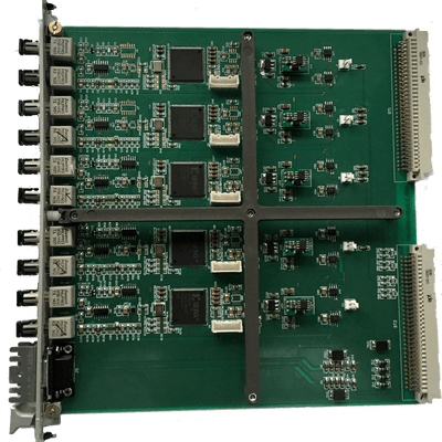
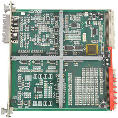
GTO Firing Pulse Card
The Fibre optical Transmitter/Receiver board is a part of the control electronics for the drive control unit. The Fibre optical Transmitter/Receiver in (LWL) AF B635 B08(GTO) converts the electrical firing pulses received from AS and NS controllers into corresponding light pulses for potential free and interference free transfer to the gate units. The feedback signal also transferred optically is converted into electrical impulses. There are 8 channels each for transmitter and receiver. For transmitter, signal level for optical logic“0” is <40 dBm and optical logic “1” is>-20dBm. Similarly signal level for receiver optical logic“0” is <-40 dBm and optical logic “1” is between -24 dBm to -12dBm
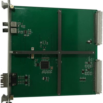
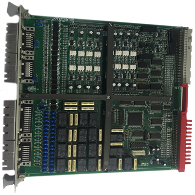
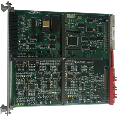
Digital I/O Card of Vehicle Control Unit
The purpose of Digital Input/output relays UR B512 boards is that digital data can be exchanged between AMS BUS and process(EMC disturbed zone). The signals from EMC disturbed zone are interfaced via sub-D front connectors to Digital Input/output board.
The EMC disturbed zone is electrically isolated from EMC protected zone and EMC computer zone by means of opto-couplers.
The Digital I/O board provides 16 inputs in two groups of eight. They are electrically isolated from each other by optical means. Due to electrical isolation of the groups, the battery power supply must be connected
separately to each input group.
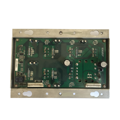
Rack Power Supply for Vehicle Control Unit
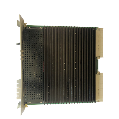
This is a multiple Power Supply with 160W DC-DC- Converter with potential isolation. It generates the Output Voltages 5V/4A, ±15V/1.5A and ±24V/2A with an input range from 66 to 154 VDC. It operates from -55 to 100°C. Its efficiency is upto 90%.
Analog I/O Card
The Analog I/O board is mainly intended to Input and Output the analog data. It filters and amplifies the analog values and makes them available on the AMS bus. The inputs can be configured (current, voltage etc.) by the user. The differential input channels are equipped with two RC low passes. The outputs of the differential amplifier (after the low pass) are lead to ST1 connector and to the test sockets.
Motor Converter Peripheral Card
This card converts the Wiegand sensor signals from 4 speed measurement devices to CMOS-logic level, simulates d.c. link current and current flowing through the MUB-resistors. Also it induces protective shutdown in case of any major failure and
thus provides converter protection.
The modified AS-peri card is able to take inputs from the latest IGBT type sensors. Also it gives provision for automatic switching of a healthy channel into another circuit, in case the speed sensor of that channel
is defective (auto switching feature). This modified AS-pericard, when provided in MICAS based locomotives having GTO converter, will be able to support both new generation of speed sensors which are used in IGBT converters
as well as the active sensors presently used in the GTO converters. This will bring in standardization and backward compatibility.
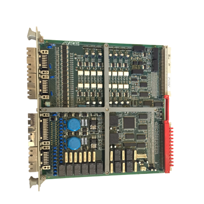
Peripheral Card for Line Converter
NS-peri card is a part of line converter control electronics in drive control unit. It performs all line current functions which cannot be controlled by main controller board. The calculation of magnetizing current of the transformer, multiplexing of GTO feedback signals are performed.
Digital I/O Card of Traction Converter
Binary I/O board is designed to support the special functions required by the Drive Inverter Control Unit in the locomotive. It contains 16 digital inputs and ten digital outputs with relays and two FET outputs. The FET output has a feature which is necessary for the protective shut-down which will be required during serious failure within ALG rack.
Rack Power Supply of Traction Converter Control Rack
This is a multiple output card with DC-DC converter having potential isolation. Output voltages of +5V/7A, ±15V/2A and ±24V/6A are produced from input voltage of 77V to 137V.
Rack Power Supply for Auxiliary Converter
This is a multiple output card with DC-DC converter having potential isolation. Output voltages of +5V/4A, ±15V/1.2A and ±24V/3A are produced from input voltage of 77V to 137V.